- Sepic converter matlab simulink model how to#
- Sepic converter matlab simulink model software#
- Sepic converter matlab simulink model code#
Sepic converter matlab simulink model software#
Simulation is carried out in MATLAB/ SIMULINK software and the results of the Cuk converter, SEPIC converter and the hybridized converter are presented. Hybridizing solar and wind power sources provide a realistic form of power generation. Vasco also worked as a control software developer for electric supercars at EVTEC. A new converter topology for hybrid wind/photovoltaic energy system is proposed. Prior to joining MathWorks in 2016, Vasco worked as a development engineer on the modelling and simulation of engines at Liebherr Machines Bulle. He collaborates with industrial automation and machineries, automotive, and medical companies. He specializes in design automation with emphasis on multidomain modelling, control design, verification, and deployment.

Vasco Lenzi is a senior application engineer at MathWorks Switzerland. Rerunning the simulation with different inductor values shows when the converter starts to operate in a discontinuous conduction model.

With a chosen inductor value simulation shows that the converter operates in continuous conduction mode. HIL testing using a Simscape Electrical model deployed to as FPGA implemented in a Speedgoat real-time target machine The model is simulated open loop with a constant duty cycle.
Sepic converter matlab simulink model code#

Sepic converter matlab simulink model how to#
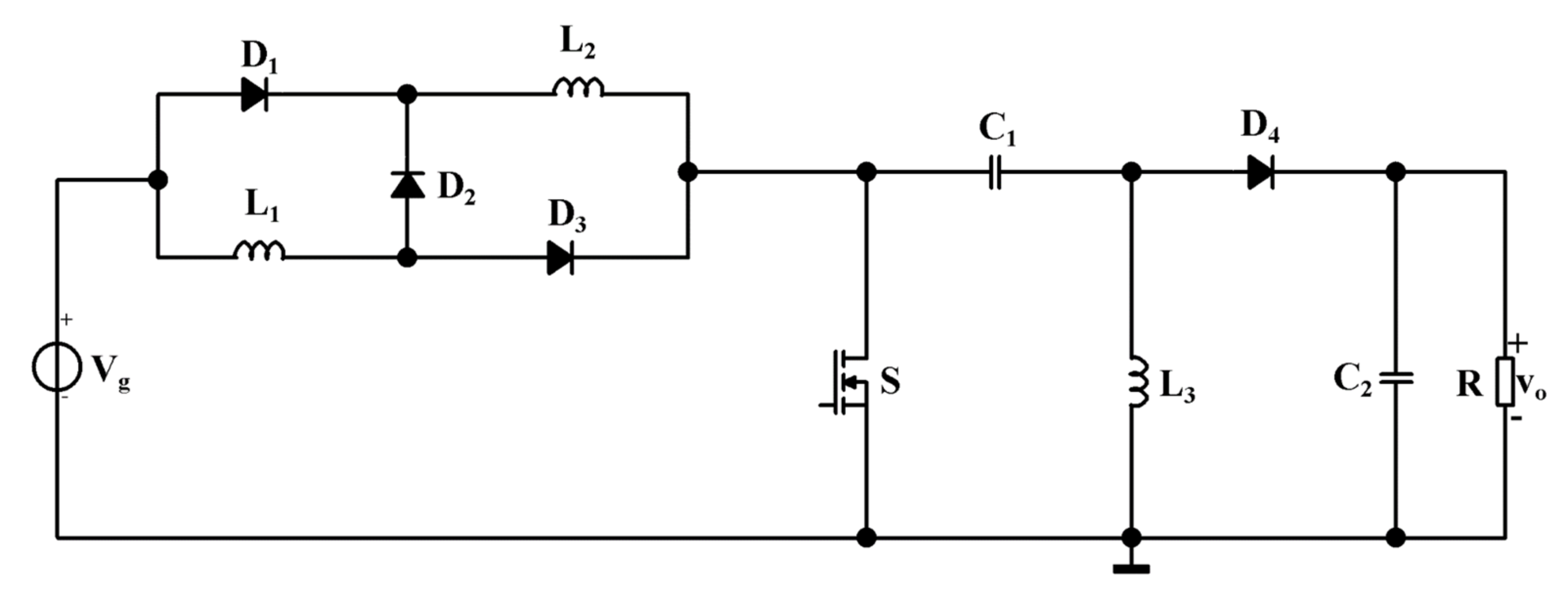
Using Simulink® and Simscape Electrical™, MathWorks engineers will show how to develop, simulate, and implement a controller that maintains desired output voltage in the presence of input voltage variations and load changes to achieve fast and stable response. The control algorithms will be used to generate embedded code optimized for implementing on a Texas Instruments™ C2000™ microcontroller. The simulation results are presented and discussed.In this webinar, we will use a SEPIC circuit topology to show how to model and simulate a DC-DC converter that powers a strip of LEDs. Control systems for maximum power point tracking and battery charge/discharge are implemented and used for simulations to study: 1) the response of the system to the ever-changing environmental variables, 2) the ability to track the maximum power point, and 3) the role of the battery energy storage in the mitigation of voltage and power oscillations. This paper develops models for an integrated PV system which comprises the PV array, the SEPIC (single ended primary inductance converter) converter, bidirectional dc-dc converter, the inverter, and battery energy storage system using Matlab/Simulink. There is a dearth of such reliable and accurate models for PV systems study. Development of Generalized Photovoltaic Model Using MATLAB/SIMULINK, Proceedings of the World Congress on Engineering and Computer Science 2008. (b) Mat lab model of modified SEPIC converter along with PV fed. (a) Mat lab model of modified SEPIC converter. Generate code from MATLAB and Simulink models optimized for embedded platforms (DSP and FPGA) System-level test using Hardware-in-the-Loop. Simulation results of modified SEPIC converter. Overcoming these challenges requires the use of computer models that accurately simulate the behavior of such systems. linear switching behavior of SEPIC converter.

The variability and intermittency associated with the production of electricity by photovoltaic (PV) systems pose unique challenges to power systems engineers.


 0 kommentar(er)
